Parameter diagram
Parameter diagram (P diagram) is a common system analysis tool, which is composed of dynamic input (including signal), factors that may affect system performance (control factors and noise factors), variation source and output (expected output and unexpected output). At the same time, the new standard adds functional, functional and non-functional requirements.
Engineers minimize the sensitivity of system elements to noise factors through control factors to improve product reliability. Provide complete functional analysis to provide the basis for subsequent failure analysis and risk analysis.
Parameter diagram (P diagram) creation
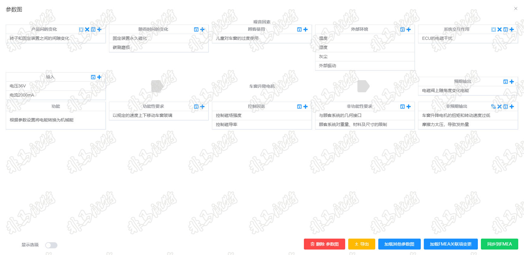
Through the FMEA Hunter parameter diagram tool, the parameter diagram can be quickly and effectively created for specific functions.
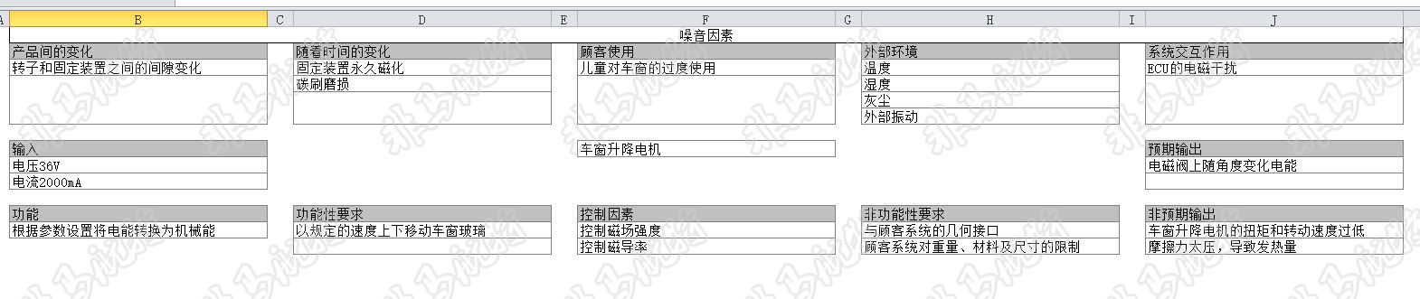
For example, the parameter diagram of the "Convert electric energy to mechanical energy according to parameter settings" function of the window lifting motor is as follows:
→ [Inputs] is the description of the signal source required to realize the system function. (such as voltage 36V, current 2000mA);
→ [Intended Output] is an ideal and expected function output. (For example, the electric energy on the solenoid valve changes with the angle);
→ [Unintended Output] refers to failure behavior or unexpected (wrong time and space) system output, which makes the system performance deviate from the ideal expected function. (For example, the torque and rotation speed of the window lifting motor are too low, and the friction force is too high, resulting in heat generation;
→ [Control Factors] are identified and can be adjusted to make the design less sensitive to noise. (such as controlling magnetic field strength and permeability);
→ [Noise Factors] refers to the parameters representing the potential significant change source of the system response. From the perspective of the engineer, these parameters cannot be controlled or it is impractical to control them. Noise factors are divided into the following categories:
■ Piece to piece variation (such as changes in clearance between rotor and fixture);
■ Change over time (such as permanent magnetization of fixed device, wear of carbon brush);
■ Customer usage (such as excessive use of windows by children);
■ External environment (such as temperature, humidity, dust, external vibration, etc.);
■ System interaction (such as electromagnetic interference of ECU);
→ [Function] In the parameter diagram, use the present tense, add a measurable noun after the active verb, and relate to the demand. (such as converting electrical energy into mechanical energy according to parameter settings);
→ [Functional requirements] is related to the performance of the function. (such as moving the window glass up and down at the specified speed);
→ [Non functional requirements] can limit the design options. (such as the geometric interface with the customer system, the customer system's restrictions on weight, material and size);
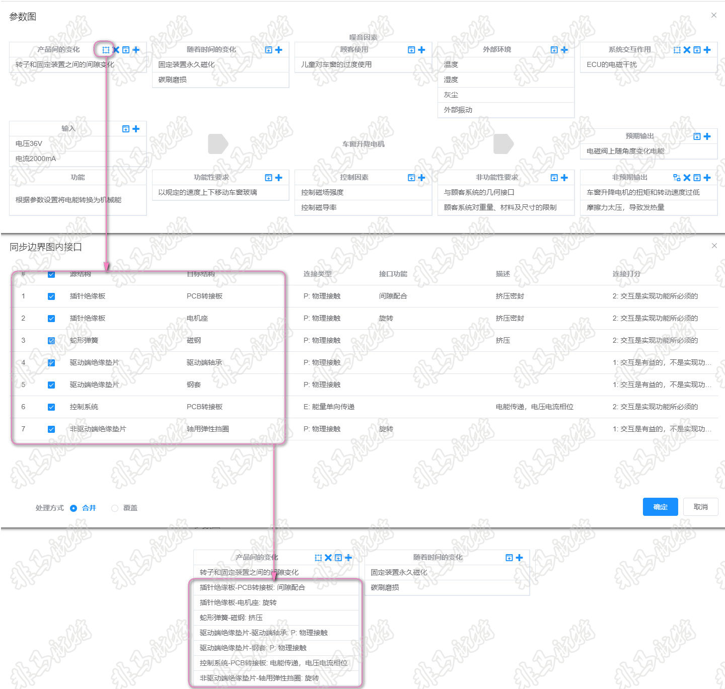
Loading Boundary Diagram Interface
The FMEA Hunter parameter diagram can directly reference the relevant interface in the boundary diagram as the corresponding factor of the parameter diagram;
The piece to piece variation come from the hardware interface inside the frame of the boundary diagram, and the system interactions comes from the hardware interface outside the frame of the block diagram.
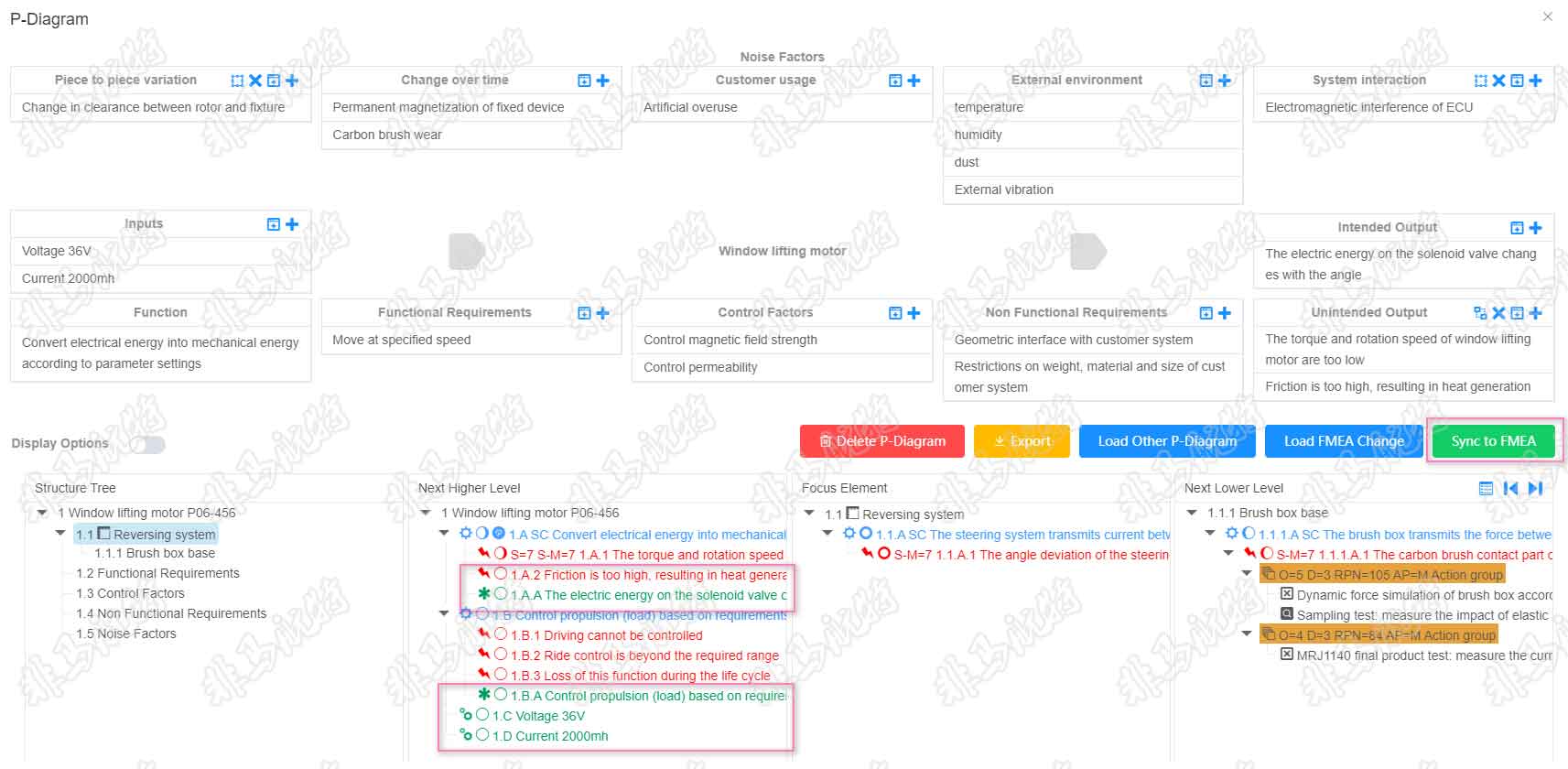
Synchronize to FMEA
After analyzing the parameter diagram for specific functions, the factors of the parameter diagram are synchronized into the FMEA through synchronous operation to provide complete functional analysis and failure analysis.
Export parameter diagram
After the parameter diagram analysis is completed, you can export the parameter diagram as an EXCEL report through the export operation.